
#100: Accurate temperature control in waterless printing with IRt/c sensors: how to increase printing speed
By Francesco Pompei, Exergen Corporation
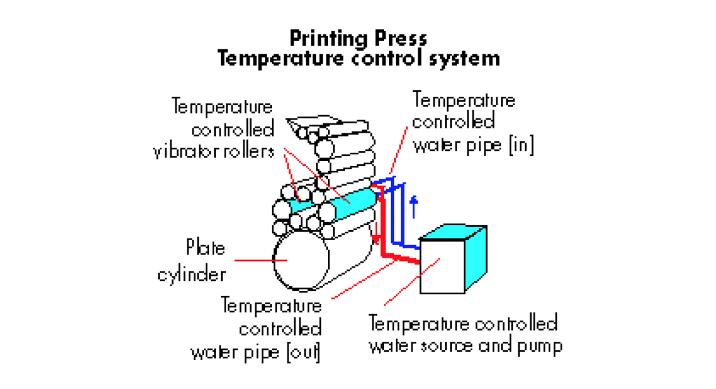
At the heart of waterless printing is the requirement for accurate temperature control of the ink roller system due to the importance of maintaining proper viscosity. A significant barrier to improvement in the quality of ink temperature control for waterless printing systems is the delay caused by the mass of the roller, especially when increasing speeds.
Water-cooled systems are particularly subject to this delay since the roll is cooled from the inside, and the entire mass of the roll must change temperature in order to control the surface, where the ink properties are, of course, determined. Air-cooled systems are less influenced by the delay, but still require an optimal control strategy to maximize speed.
At the heart of the temperature control are non-contact infrared sensors that are designed specifically for the waterless printing application. One such model is the IRt/c-WP series from Exergen, which is the most accurate available. The discussions below use these sensors.
Water-Cooled Systems
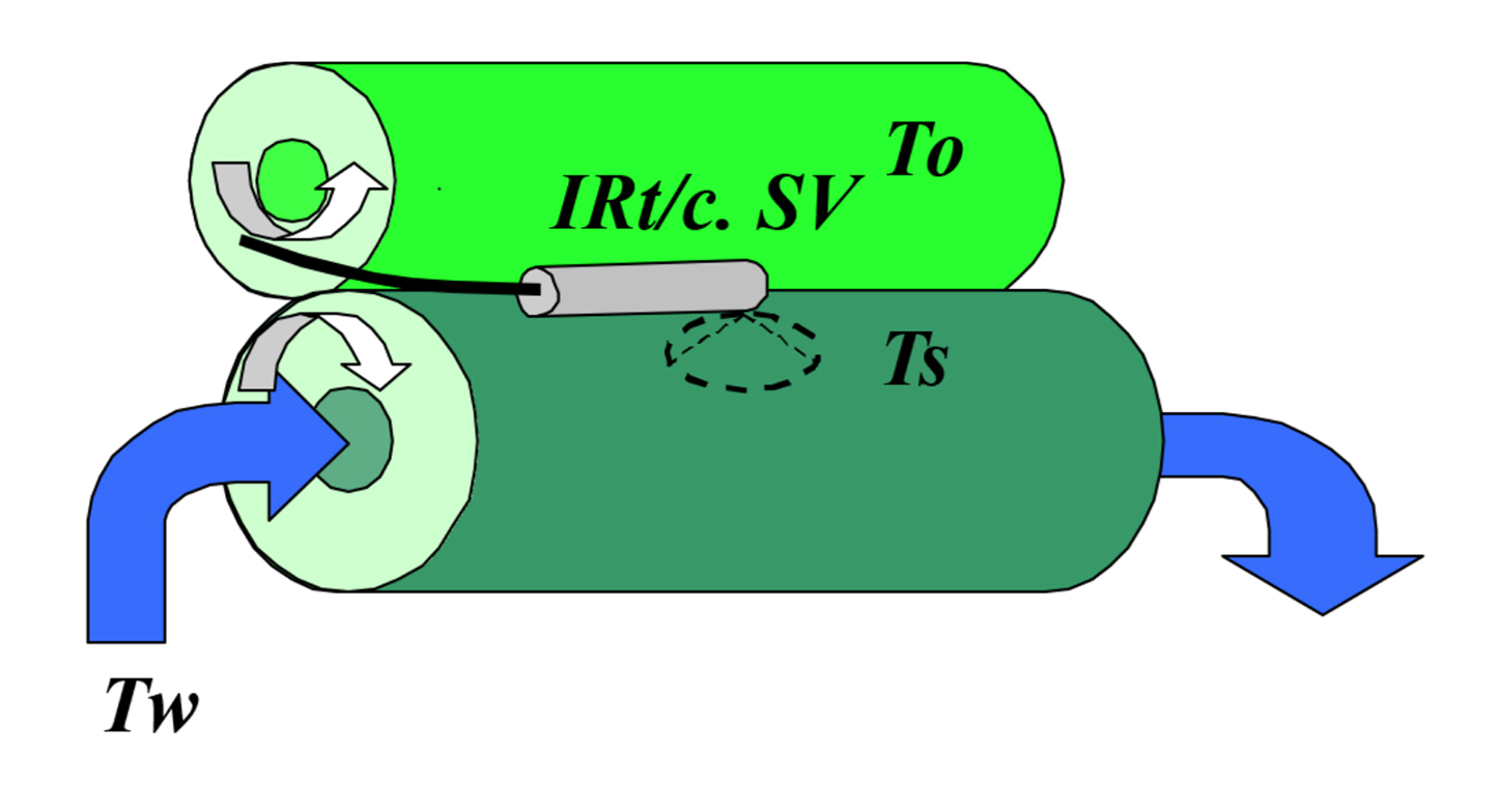
A change in temperature on the cooled roller outside surface Ts, will be sensed by the IRt/c infrared sensor within a tenth of a second, and the correction to the water cooling temperature Tw will occur within a few seconds. However, the entire mass of the roll must change temperature from the inside-out before the surface can change and thus correct the temperature of the ink – a process requiring several minutes. The several minutes that the temperature is incorrect may cause reduced quality printing, and thus prevent operation at higher speeds.
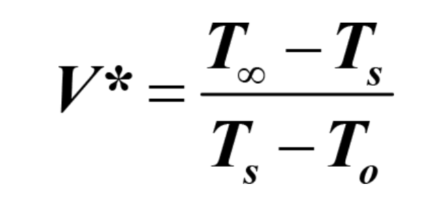
The remedy for this problem is the application of the Speed Boost Equation™ (see www.cleverir.com for details):
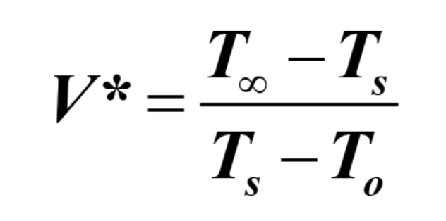
where V* is relative speed, T∞ is the temperature of the energy source, Ts the temperature of the surface, and To the temperature of the feed material into the process. For the example in the diagram, the cooling water Tw is the energy source.
Accordingly, if the speed of the roll V is measured and available to the temperature control system, the Speed Boost Equation then becomes:
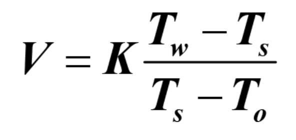
where K is a proportionality constant.
Then the control equation for the water temperature Tw becomes:
Accordingly, any change in V should be accompanied by an immediate change in Tw in accordance with the above equation. In the same manner, a control loop gain in response to a change in Ts at constant V can be immediately established by selecting (1+V/K), taking care to account for the offset ((-V/K)*To). This strategy assumes that the ink feed temperature To is sufficiently constant to be treated as constant.
Adding the control loop PID contribution to correct the value of Tw in response to minor perturbations, we end with which is the governing control equation.
Variable Feed Roll Temperature To
As is the case in many high performance installations, the feed roll temperature is not always constant, since friction from the rolls will gradually warm the rolls. Accordingly, to further improve performance, the addition of a second IRt/c is recommended to monitor the feed roll temperature To. With this additional sensor, equation 4 is again employed, but To is treated as variable and its value measured by a second IRt/c. This measure is recommended when the quantity in the denominator of equation 2 (Ts-To) is less than ~ 10°C (16°F), and is greater than the quantity in the numerator (Tw-Ts). This situation will exist as the speed V is increased and the heat transfer characteristics of the roll are improved.
Maximal Speed and Performance Strategy
For maximum print speeds at maximum quality, the quantities (Tw-Ts) and (Ts-To) must be accurately controlled under all conditions. The PID feedback control is not sufficient since at maximum speeds the feedback requires significant time to respond due to the thermal lag of the roller from the inside to the outer surface, and will produce ink temperature errors and thus poor quality.
The IRt/c sensors provide an elegantly simple and robust method of achieving the maximal accuracy by employing their inherent thermocouple character. Rewriting equation 4:
We see that the critical temperatures for control are the differences (Tw-Ts) and (Ts-To), with the PID feedback a small trim on the setpoint of Ts. From basic thermocouple characteristics we can directly measure these temperature differences with accuracy of order 0,1°C (0.2°F) by simply wiring IRt/c’s differentially as common thermocouples.
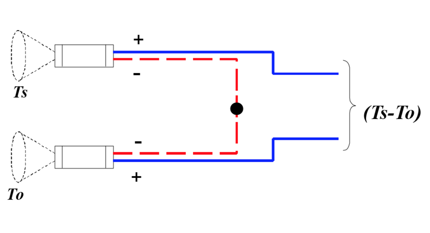
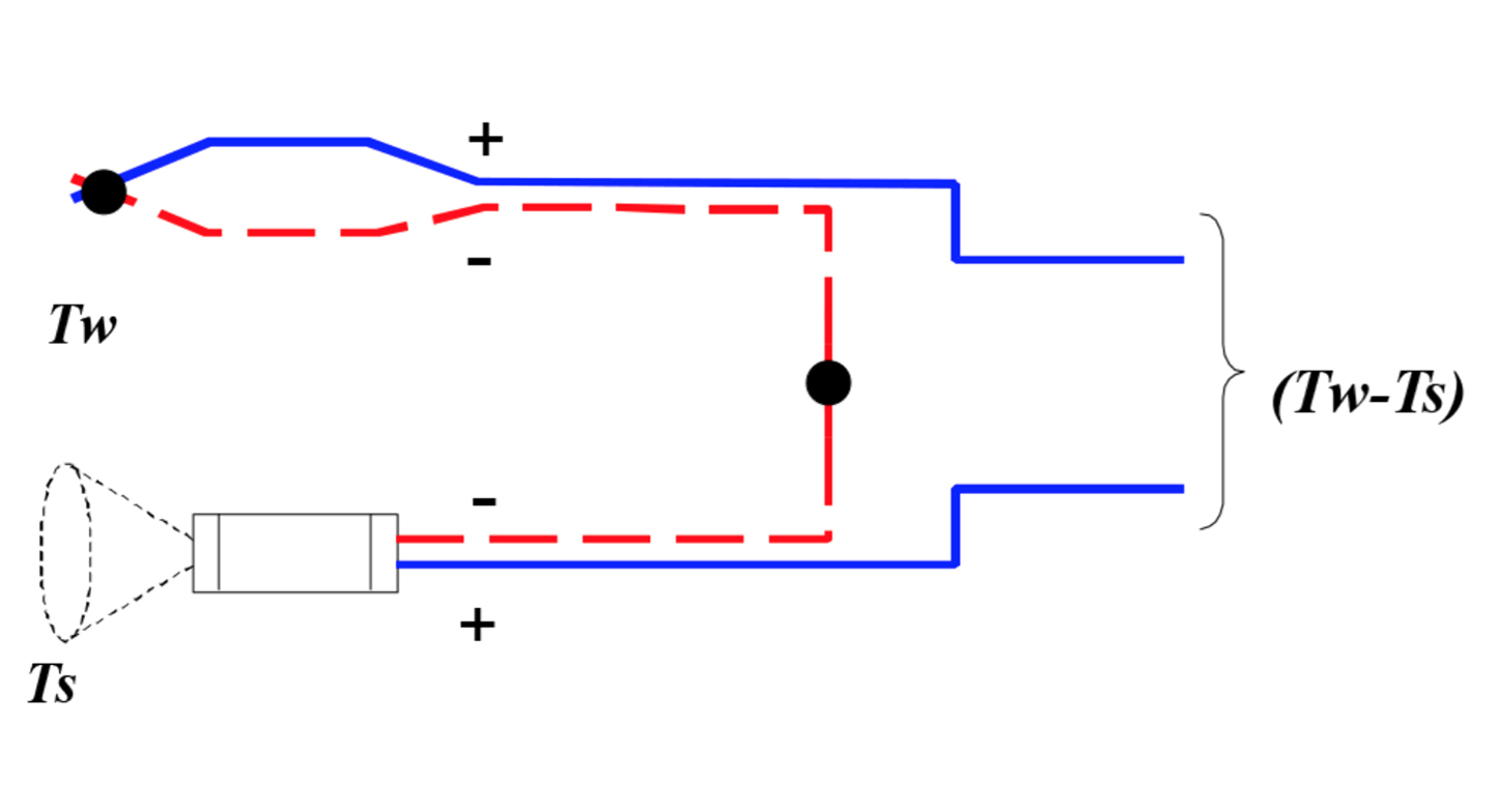
Further, the feed water temperature Tw may be measured by an ordinary immersion thermocouple, then wired in series with an IRt/c monitoring Ts to produce a direct signal for (Tw-Ts).
The end result from the application of the Speed Boost Equation is balanced cooling input that correctly adjusts the flow of heat to maintain consistent balance in the heat into and out of the roll surface. With this balance, temperature control is maintained accurately, and speed may be increased to maximal values permissible by the press without loss of quality.
Air-Cooled Systems
Air cooling systems have the significant advantage that there is less delay in response to a cooling load change, since only the immediate surface must change temperature. However, the roll does require re-establishment of distribution of temperature around the roll as conditions change, especially speed, and therefore optimal control requires the Speed Boost method.
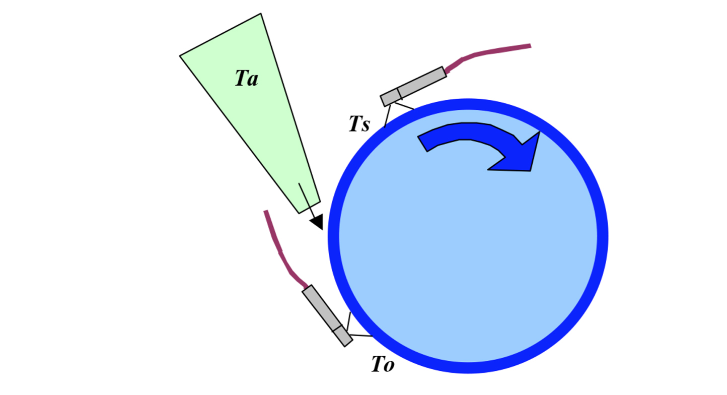
Air-cooled arrangement showing two IRt/c’s monitoring the roll surface temperature just prior to the air jet (To) and just after the air (Ts). The air supply temperature (Ta) can be monitored with a standard thermocouple.
Applying again eq. 1,
and referring to the temperatures in Figure 6, the equation can be re-written as
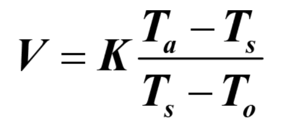
where K is the proportionality constant.
Then the control equation for the air temperature Ta becomes:
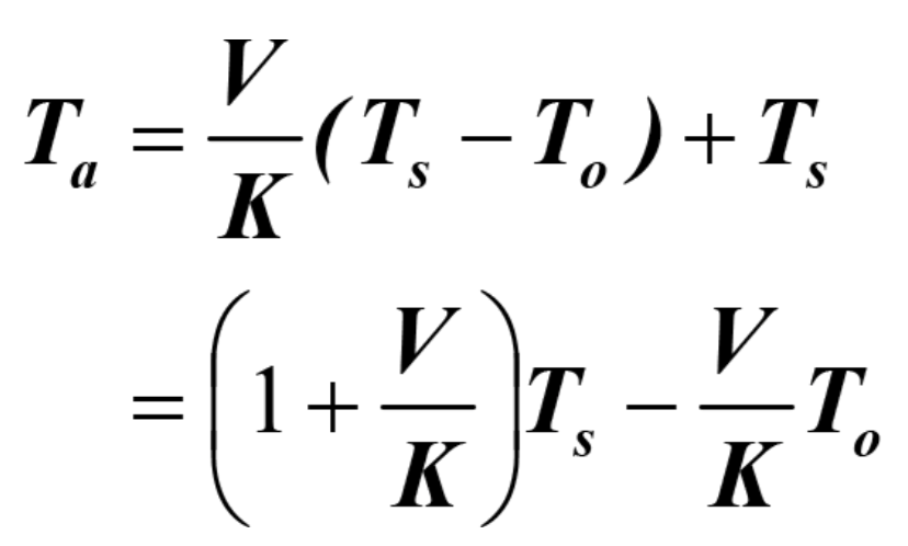
Accordingly, any change in V should be accompanied by an immediate change in air temperature Ta in accordance with the above equation.
Adding the control loop PID contribution to correct the value of Ta in response to minor perturbations, we end with
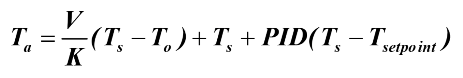
which is a form of governing control equation that can be applied. The differential IRt/c wiring illustrated in Figures 4 and 5 is the method of choice to assure highest possible performance in controlling for quality and speed. By adding the air temperature Ta as a thermocouple, and a second IRt/c for Ts, then the governing equation becomes
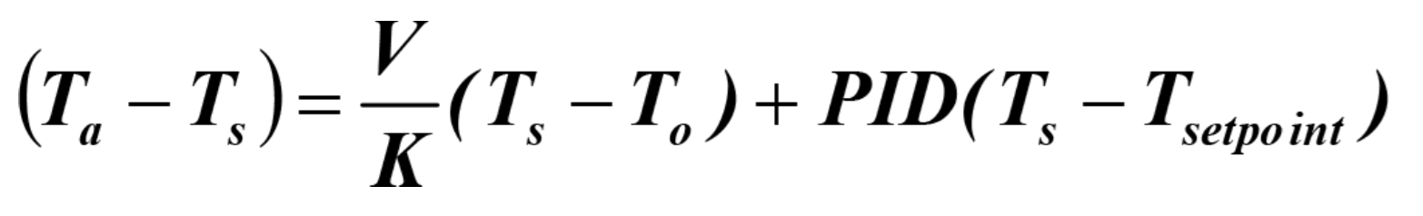
and the performance is the highest possible speed with the best possible quality.
.png)